
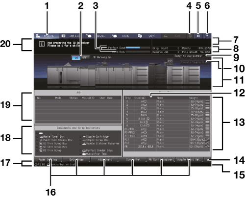
Components of the MACHINE Screen
The display of the MACHINE screen varies depending on the model you use.
This section describes ineo 6136 or ineo 6120 as well as the MACHINE screen to be displayed on the machine mounted with the options as described below.
Large Capacity Post Inserter PI-PFU, Relay Unit RU-518, Integrated Color Care Unit IQ-501, Relay Unit RU-510, Folding Unit FD-503, Saddle Stitcher SD-513, Perfect Binder PB-503, and Finisher FS-532 are displayed as optional output devices.
|
No. |
Name |
Description |
|---|---|---|
|
1 |
MACHINE tab |
Displays the MACHINE screen. |
|
2 |
Perfect binder heater switch |
Turns ON or OFF the PB (perfect binder) heater. If you know when to use the perfect binder in advance, turn it ON so that you can work efficiently. When you do not use the heater, turn it OFF to prevent the deterioration of glue. |
|
3 |
Perfect binder/main body warming-up status bar |
Indicates the warming-up status while the perfect binder or main body is warming up. When the warming up operation is completed, the status bar disappears. |
|
4 |
Web Browser |
Displays a Web browser on the touch panel. If the machine is connected to the Internet, you can view external web pages. |
|
5 |
Info. Sound/Voice ON/OFF |
Press this to temporarily turn the speaker sound off. This is available only when Speaker Sound is set to ON by selecting UTILITY - User Setting - System Setting - Operation/Info.Sound Setting - Volume Setting. |
|
6 |
Help |
Displays the help message which provides information about the screen currently
displayed. Depending on the screen,
When the MACHINE screen is displayed, Help displays the method to replace a toner bottle or waste toner box, add staples, dump staples, punch, or trim scraps, supply glue pellets, load paper, and replenish water to the humidifier tank. |
|
7 |
Output information indicator |
Displays the print count, set count, and job number of the current job while printing. |
|
8 |
Machine management information indicator |
The left side displays the original counter and the number of reserved jobs (unit: number). The right side displays the remaining amount of memory and the file system (unit: %). With the Auto Inspection Unit UK-301 connected, two items with less remaining amount among the five items (memory and file system in the main body, memory in the Auto Inspection Unit UK-301, reference image memory, and inspection report memory) are displayed. Items other than the remaining amount of the file system in the main body can be indicated in GB as needed. |
|
9 |
Scanner message |
Displays the status of the original scan of the Dual Scan Document Feeder (ADF) or Original glass. |
|
10 |
Execute Sample Print |
Makes a sample print during an output job. For details, refer to Overview of Sample Print. |
|
11 |
Machine configuration display |
Displays the configuration of main body and options. |
|
12 |
Size (mm) / Size (inch) |
The sizes are displayed in millimeters by default. Switching between millimeters and inches can be made from the UTILITY screen. For details, refer to Unit Setting. |
|
13 |
Tray information indicator |
Displays paper size, orientation, name, weight, and paper amount in the tray. |
|
14 |
Machine function keys switch |
Switches the display of the machine function keys. |
|
15 |
Machine status indicator/right |
Displays Fuser (Env.), USB Drive, Toner, PM Call, ADF Clean, Consumable, Torque, Security, Modem Err, FusingWeb, ORU-M, Waste, and Dark Tone. Up to 4 indicators can be displayed in large size. When 5 or more indicators are displayed, small icons without texts will substitute for the indicators from the 4th and onward. The maximum number of items displayed is a total of 7, including 3 normal-sized icons and 4 small-sized icons. |
|
16 |
Machine function keys display area |
Paper Setting: Press this button when specifying paper conditions for Main Body Trays, Paper Feeder Unit PF-709, Paper Feed Unit PF-710, Large Capacity Post Inserter PI-PFU, upper tray / lower tray of Post Inserter PI-502, upper tray / lower tray of Post Inserter of Folding Unit FD-503, and Cover Tray of Perfect Binder PB-503. Both Sides: Press this button to perform the front side and back side adjustments of a print image on paper loaded in each tray (Tray1 to Tray11), rotate/skew adjustment, chart adjustment, gap adjustment, and scan measurement adjustment. Adjustment: Adjusts the main body and optional equipment. Controller: Configures the controller. RU Curl Adjustment: Press this button to when configuring curl adjustment for each tray (Tray1 to Tray11, and PI-PFU1 to PI-PFU3). When Humidifier HM-103 is mounted on Relay Unit RU-518, you can make the humidification setting for each tray. Sample Print Set.: Pressed to set sample print. The following buttons are displayed when the Machine function keys switch is pressed. Color Dens. Manual: Press this key to manually adjust the color density or manage the registered information for Color Density Manual Control. When Use Color Density Control is set to ON, this key is enabled. Color Dens. Result: Press this key to check the periodic adjustment result of Color Density Control. When the periodic adjustment is conducted, this key is enabled. Reg./Del.PaperSet.: Press this key to register or delete the frequently used paper setting. IQ Detected Result: Press this key to display the result detected as an error when Integrated Color Care Unit IQ-501 is mounted. User's Guide: Press this key to display the User's Guide. The following buttons are displayed when Auto Inspection Unit UK-301 is mounted. AutoInspect.Report: Press this key to display the result of automatic inspection. Ref. Image Manage.: Press this key to manage the previously created reference images. Memory Status: Press this key to check the amount of available memory space of the Auto Inspection Unit UK-301. IQ Function Set.: Press this key to specify inspection standards and operations to be performed when an image failure is detected. |
|
17 |
Machine status indicator/left |
Displays the current time or the status of the image controller. |
|
18 |
Consumable and Scrap Indicators area |
Displays the current status of toner supply. Also, this area lights red to prompt a user to replace the waste toner box, add staples to the optional unit, dump scraps, and replenish water to the humidifier tank. The number of replacements of the toner bottle can be counted. For details, contact your service representative. |
|
19 |
JOB LIST |
Displays the current status of the jobs to be operated on the machine. When there are any incomplete jobs, the Incomp. History key is displayed. |
|
20 |
Message area |
Displays messages concerning the current status of the machine or operation currently required. |
 may be shaded and no help
message can be displayed.
may be shaded and no help
message can be displayed.